

Views: 0 Author: Site Editor Publish Time: 2026-10-10 Origin: Site


Delayed time-to-market drains capital. Moving to full production with unvalidated metal components risks catastrophic failure. Engineering teams constantly battle this tension. They need physical validation fast. Rapid prototyping solves this problem by strategically deploying advanced fabrication techniques. It transitions a three-dimensional CAD design directly into a functional, physical component. Procurement and engineering departments often struggle to balance speed, dimensional accuracy, and material fidelity during this transition. A structured rapid prototyping workflow bridges the gap between digital models and physical reality. It mitigates production risks while accelerating engineering validation and stakeholder approval. You will learn how to align fabrication methods with validation stages, enforce early manufacturability rules, and seamlessly scale from initial models to final production runs.
Align Method with Validation Stage: Selecting the right fabrication method (CNC, additive, or sheet metal) depends strictly on whether the goal is form/fit evaluation or rigorous functional testing.
DFM is Non-Negotiable Early On: Design for Manufacturability (DFM) must be integrated during the prototyping phase to prevent costly redesigns when scaling to production.
Material Fidelity Matters: Prototyping materials should closely mirror end-use production materials to ensure accurate thermal, mechanical, and stress testing.
Workflow Standardization Reduces Risk: A formalized process from CAD review to post-processing prevents lead-time creep and cost overruns in custom metal prototype machining.
Engineering teams must establish clear validation goals before cutting any material. Prototyping is not a monolithic phase; it breaks down into distinct stages based on what needs testing. Conceptual models serve as visual representations. They allow industrial designers and stakeholders to evaluate ergonomics, aesthetics, and general proportions. However, conceptual models rarely possess the mechanical strength required for real-world application. Form and fit prototypes take the next step. They verify assembly tolerances, ensuring that mating parts align correctly without interference. This stage exposes stack-up tolerance issues that look fine on a computer screen but fail on the assembly bench.
Functional prototypes represent the most rigorous validation stage. These components undergo load testing, thermal cycling, and environmental stress exposure. If a bracket must hold a 50-kilogram load under continuous vibration, the prototype must survive that exact scenario. Rapid iteration at this stage reduces overall development costs. Identifying a structural weak point during the functional prototype phase costs a fraction of what it takes to modify hardened steel production tooling later. Tangible, high-fidelity models also secure early stakeholder and investor buy-in by proving the engineering concept works in reality, not just in simulation.
Engineers constantly navigate the trade-off between speed and fidelity. You can print a plastic representation of a part in a few hours, but it will not yield accurate thermal conductivity data. Achieving production-grade material properties and tight tolerances takes more time. Machining a prototype from a solid billet of aerospace-grade aluminum requires programming time, custom workholding, and specialized tooling. The delay is necessary when the validation criteria demand exact material behavior. Skipping this step leads to false positives in testing.
The cost of failure in manufacturing scales exponentially as a product moves toward launch. Inadequate prototyping leads to expensive tooling modifications. If a die-cast mold is cut based on an unvalidated design, fixing a misplaced boss or an incorrect draft angle requires welding, re-machining, and re-polishing the tool. This delays product launches by weeks or months. A rigorous prototyping phase acts as an insurance policy against these late-stage disasters, ensuring the design is fully locked and proven before mass production begins.
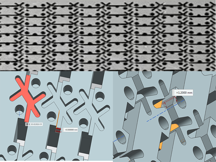
Selecting the correct manufacturing process is the most critical decision in the prototyping workflow. When engineering Custom Metal Parts, the chosen method dictates the lead time, cost, and physical characteristics of the final component. The three primary fabrication methods each serve specific engineering requirements and come with distinct operational constraints.
Computer Numerical Control (CNC) machining remains the industry standard for high-precision requirements. It involves removing material from a solid block using high-speed rotary cutters. CNC machining is the best application for parts requiring tight tolerances, excellent surface finishes, and functional testing using production-grade billets. Because the prototype is cut from the exact same wrought material as the final product, the mechanical properties are identical. This method is frequently used to create CNC machined metal test fixtures. These fixtures validate assembly processes and structural integrity early in the lifecycle, providing a rigid, accurate platform for holding components during inspection or secondary operations.
Sheet metal fabrication offers a completely different approach, focusing on manipulating flat stock. This method is the best application for enclosures, brackets, chassis, and panels. The process utilizes laser cutting, punching, bending, and stamping to create functional parts quickly. When prototyping sheet metal, engineers must evaluate tooling limitations and bend radii constraints. A common mistake is designing a bend radius tighter than the material thickness allows, leading to cracking along the bend line. Rapid turnarounds in sheet metal require standardizing hole sizes to match available punch tooling and avoiding complex forming operations that require custom dies.
Metal Additive Manufacturing, commonly known as 3D printing, builds parts layer by layer. Technologies like Direct Metal Laser Sintering (DMLS) and Selective Laser Melting (SLM) fuse metal powder using high-powered lasers. This method excels at producing complex geometries, internal conformal cooling channels, and lightweight lattice structures that are physically impossible to machine. However, engineers must understand the trade-offs. Metal 3D printed parts often have a rougher surface finish compared to machined parts and may exhibit structural anisotropy, meaning their mechanical properties vary depending on the build direction. They also require significant post-processing to remove support structures and improve mating surfaces.
Fabrication Method | Best Application | Primary Advantages | Key Limitations |
|---|---|---|---|
CNC Machining | High-precision functional prototypes, test fixtures, load-bearing components. | Exceptional dimensional accuracy, identical material properties to production, superior surface finish. | Geometry limited by tool access, higher cost for complex organic shapes, requires custom workholding. |
Sheet Metal Fabrication | Enclosures, brackets, chassis, structural panels. | Fast turnaround for flat and bent parts, highly scalable to production, cost-effective for large footprints. | Restricted to uniform wall thickness, limited by standard bend radii, complex forms require custom tooling. |
Metal Additive (3D Printing) | Complex internal geometries, lightweighting, consolidated assemblies. | No tooling required, absolute geometric freedom, rapid iteration of complex shapes. | Rough surface finish, potential internal porosity, requires extensive post-machining for tight tolerances. |
Executing a successful prototype requires a disciplined, phased approach. Skipping steps to save time usually results in scrapped parts and extended lead times. The workflow moves logically from digital optimization through physical fabrication and final inspection.
Phase 1: CAD Optimization and DFM Review. The process begins with a rigorous technical review of the three-dimensional CAD models. Manufacturing engineers analyze the geometry to identify features that will cause fabrication issues. They look for deep pockets with small radii that require specialized long-reach tooling, which induces chatter and poor surface finish. They flag undercuts that cannot be reached by standard 3-axis or 5-axis machines. Non-standard thread sizes are identified and replaced with standard unified or metric threads to avoid custom tap purchases. The goal is to adjust the design to match the chosen rapid manufacturing process while maintaining the original design intent.
Phase 2: Material Selection and Sourcing. The prototype material must match the end-use requirements as closely as possible. If the final part will be die-cast aluminum, prototyping in Aluminum 6061-T6 provides a reasonable approximation of mechanical strength, though the grain structure differs. For highly corrosive environments, Stainless Steel 304 or 316 is selected. Titanium is chosen for aerospace applications requiring high strength-to-weight ratios. Navigating supply chain availability is critical here. Rapid-turn raw materials must be sourced locally or kept in stock. Specifying an exotic alloy for a prototype can add weeks to the lead time simply waiting for the material to arrive at the machine shop.
Phase 3: Fabrication and In-Process Quality Control. Once the material is secured and the CAM programming is complete, fabrication begins. Advanced machining techniques, such as high-speed dynamic milling, are utilized to remove material rapidly while minimizing heat generation and tool wear. Continuous monitoring is essential. Machinists check critical dimensions while the part is still in the machine to ensure tolerances are being met before the final finishing passes. Utilizing First Article Inspection (FAI) principles at the prototype stage ensures dimensional accuracy. Coordinate Measuring Machines (CMM) and optical comparators verify that the physical part matches the digital model exactly.
Phase 4: Post-Processing and Surface Finishing. A prototype is rarely finished when it comes off the machine. Post-processing applies the necessary treatments to replicate the final product's performance and aesthetics. Bead blasting removes tool marks and provides a uniform matte finish. Anodizing (Type II or Type III) adds corrosion resistance and surface hardness to aluminum parts. Powder coating provides a durable, colored finish for sheet metal enclosures. Heat treatment may be required to relieve internal stresses induced during machining or to achieve specific hardness requirements for functional testing. Engineers must account for the dimensional changes caused by these coatings when designing the initial CAD model.
Prototyping is not an isolated event; it is the precursor to mass production. Evaluating the prototype involves mapping specific features to long-term product outcomes. If a tapped hole strips during assembly testing on the prototype, the thread engagement length must be increased before production tooling is finalized. Every failure or marginal pass during the validation stage provides data to refine the production design.
Assessing the scalability of the prototyping method is a primary engineering responsibility. A part designed specifically for 3D printing might be impossible to manufacture economically at scale. Engineers must evaluate whether the design can transition into manufacturing low volume precision metal parts using traditional methods like CNC machining or casting. If the geometry relies entirely on additive manufacturing, the unit cost will remain high regardless of volume.
Bridge tooling integration offers a practical middle ground between single-unit prototypes and full-scale production runs. Instead of jumping directly to hardened H13 steel molds for injection molding or die casting, engineers utilize intermediate soft tooling. Aluminum molds can be machined quickly and cost-effectively. They withstand enough cycles to produce hundreds or thousands of parts, allowing for extensive field testing and initial market release while the hard tooling is being fabricated.
Cost-per-part analysis dictates the transition points between manufacturing methods. At a quantity of one to fifty, CNC machining or 3D printing is highly economical because there are zero tooling costs. As volumes increase to the thousands, the high cycle time of machining makes it cost-prohibitive. At this inflection point, investing in stamping dies, extrusion profiles, or casting molds becomes necessary. The prototype phase must validate the design sufficiently to justify these heavy capital expenditures.
Regulatory and compliance considerations heavily influence the scaling process. Prototype partners must adhere to industry-standard quality management systems, such as ISO 9001 for general manufacturing or AS9100 for aerospace applications. Traceability is mandatory. Material test reports (MTRs) and certificates of conformance must accompany the prototypes to prove that the specified alloys were actually used. This documentation is critical when submitting the final product for regulatory approval, such as FDA clearance for medical devices or FAA certification for aircraft components.
Engineers sometimes design parts optimized solely for the prototyping process. A common scenario involves designing a highly complex, organic shape that is easily 3D printed but physically impossible to machine or cast. When it comes time to scale production, the entire part must be redesigned, invalidating all previous functional testing. Mitigation requires enforcing strict DFM guidelines based on the final intended production method from day one. If the part will ultimately be die-cast, the prototype must be designed with uniform wall thicknesses, appropriate draft angles, and no undercuts, even if it is being CNC machined for the validation phase.
The actual machining of a prototype might take two days, but outsourced finishing, heat treating, or specialized coatings can add three weeks to the schedule. Shipping parts between multiple vendors introduces logistical delays and increases the risk of damage or loss. Mitigation involves consolidating operations with a single-source manufacturing partner who handles machining, inspection, and finishing in-house. Alternatively, engineers can select standard, readily available finishes for early-stage prototypes. Skipping the custom color anodize in favor of a standard clear coat or raw machined finish drastically reduces turnaround time without compromising functional mechanical testing.
Over-tolerancing parts is a widespread engineering habit that destroys prototyping budgets and timelines. Applying a blanket +/- 0.001-inch tolerance to every dimension on a drawing forces the machinist to slow down feed rates, use specialized tooling, and perform exhaustive CMM inspections on non-critical features. This leads to unnecessary costs and rejected prototypes for dimensions that do not affect part function. Mitigation requires standardizing tolerances early. Apply tight tolerances only to critical mating surfaces, bearing presses, and functional interfaces. Use standard block tolerances (such as ISO 2768-m) for all other dimensions to allow for faster, more economical fabrication.
Compile your native CAD files and generate detailed 2D drawings that clearly define all critical dimensional tolerances and surface finish requirements.
Define your exact material requirements, including specific alloy grades and temper states, based strictly on the functional testing the prototype will undergo.
Request a comprehensive Design for Manufacturability (DFM) review from a qualified manufacturing partner to identify unmachinable features before issuing a purchase order.
Establish clear inspection criteria and request a First Article Inspection (FAI) report for the initial prototype delivery to verify dimensional compliance.
A: Lead times typically range from 3 to 14 days. This timeframe depends heavily on part complexity, raw material availability, and required secondary finishes. Simple 3-axis milled parts can be turned around in a few days, while complex 5-axis components requiring heat treatment and custom anodizing will push toward the two-week mark.
A: The primary advantage is the ability to quickly validate form, fit, and function, drastically reducing overall development costs and preventing late-stage tooling errors. The main challenge is ensuring the prototype's material properties and manufacturing methods accurately reflect the final mass-produced part to avoid false positives during testing.
A: CNC machining is best for achieving tight tolerances, superior surface finishes, and standard wrought material properties. 3D printing excels at producing complex, unmachinable geometries, internal channels, and rapid iterations without the need for custom workholding or tooling.
A: Yes, bridge tooling or soft tooling, such as aluminum molds, can often be utilized to produce low-volume runs. This provides a highly cost-effective middle ground, allowing for market testing and initial production before investing heavily in hardened steel production molds.
A: Standard rapid CNC machining can typically hold tolerances of +/- 0.005 inches. Tighter tolerances, down to +/- 0.001 inches or better, are available upon request for critical features like bearing bores or mating surfaces, though this will increase both cost and lead time.
A: A DFM review identifies design flaws, such as deep pockets, undercuts, or non-standard threads, that could cause manufacturing failures. It ensures the prototype can actually be produced efficiently and scaled to mass production later without requiring a complete redesign.
A: They are used to securely hold prototype components during assembly, inspection, or functional testing. These fixtures ensure repeatable and accurate validation of the part's design by providing a rigid, dimensionally stable platform that eliminates measurement variables.


