

Views: 0 Author: Site Editor Publish Time: 2026-10-04 Origin: Site


Dimensional non-compliance directly impacts operational stability. A single oversized shaft halts assembly lines, forcing rework and production delays. Out-of-spec rotational components cause field failures in high-stakes applications like aerospace actuators or high-pressure hydraulic systems. Manufacturing teams face a rigorous challenge. You must balance high inspection throughput with strict geometric and dimensional tolerance requirements inherent to complex rotational geometries.
Engineering and procurement teams must evaluate, select, and audit dimensional inspection methods. Relying on basic shop-floor tools fails modern precision manufacturing standards. You need a systematic approach to guarantee part viability, minimize material scrap, and ensure reliable supplier quality across high-volume production runs. This guide breaks down how to match inspection technologies to specific tolerance thresholds, control environmental variables, and implement robust quality validation protocols for CNC Turning Parts.
Match Method to Tolerance: Select inspection equipment based on the 10:1 gauge maker's rule; utilize micrometers for standard checks and Coordinate Measuring Machines (CMM) for critical tolerances.
Design for Inspection (DFI): Ensure engineering drawings establish clear, accessible datums to facilitate accurate and repeatable measurement of CNC turning cylindrical components.
Account for Material Variability: Factor in thermal expansion coefficients and cross-material measurement variability (especially when comparing tactile probing on hardened alloys versus soft polymers).
Prioritize Form Over Just Size: Rely on dedicated roundness and cylindricity systems, rather than standard calipers, to verify the true geometric form of rotational components.
Control the Environment: Standardize thermal conditions (typically 20°C/68°F) to mitigate calibration drift and measurement uncertainty during final inspection.
Measurement setups must mirror CAD models and original engineering drawings exactly. You cannot inspect a part accurately if the physical measurement datums do not match the design intent. When engineers establish primary, secondary, and tertiary datums, the inspection equipment must fixture the part using those exact same reference points. Deviating from the designated datum structure introduces immediate measurement error. We see this frequently when a shop uses a three-jaw chuck for inspection instead of a precision V-block specified by the datum scheme. The resulting data is useless.
Design for Inspection (DFI) plays a major role in early-stage engineering. You must optimize part design so that critical features on precision CNC turned shafts remain physically accessible. Probes, micrometers, and optical sensors need clear paths to engage the surfaces without interference from adjacent flanges or deep undercuts. If a feature cannot be reached by standard metrology equipment, you incur significant costs developing custom gauges or sectioning parts for destructive testing.
Simple dimensional accuracy covers basic two-point measurements like outer diameter and overall length. Complex geometric accuracy dictates form, orientation, and location. You must strictly differentiate between the two during the inspection planning phase. A part can easily pass a basic diameter check with a micrometer while completely failing a cylindricity requirement due to machine vibration or excessive chucking pressure.
Unique GD&T challenges apply directly to CNC turning cylindrical components. Concentricity, total runout, and straightness require specific, dynamic measurement strategies. Verifying total runout requires rotating the part on a datum axis while a dial indicator or probe measures surface deviation across the entire cylindrical feature. Understanding these GD&T symbols ensures you deploy the right tool for the specific geometric control required.
Measurement uncertainty represents the margin of doubt in any measurement result. False accepts mean shipping out-of-spec parts to the assembly line or the end customer. This creates massive operational risk, potential recalls, and damaged reputations. Conversely, false rejects mean scrapping perfectly good components that actually met the engineering specifications. Both scenarios destroy profit margins and inflate production costs.
You must establish Acceptable Quality Limits (AQL) to define the maximum number of defective units allowed in a batch before the entire lot is rejected. Baseline success metrics for production runs depend heavily on capability indices like Cp and Cpk. A Cpk value of 1.33 or higher proves your machining process remains stable and capable of producing parts well within the tolerance limits. This drastically reduces the need for 100% manual inspection.
To establish a reliable AQL process, follow these steps:
Identify the critical-to-function dimensions on the engineering drawing.
Determine the batch size and select the appropriate inspection level from standard sampling tables.
Assign a specific AQL percentage based on the application risk.
Pull the randomized sample from the production run.
Inspect the sample using calibrated equipment and record all variable data.
Accept or reject the entire batch based on the number of non-conforming parts found in the sample.
Digital Vernier calipers and outside micrometers remain fundamental shop-floor staples. They offer quick, immediate checks during active machining setups. However, they carry inherent limitations regarding precision and operator dependency. Calipers are subject to Abbe error and jaw deflection, making them unsuitable for tolerances tighter than 0.02mm. Micrometers provide better accuracy but require a consistent feel or the use of a ratchet thimble to ensure uniform measuring pressure. An inexperienced operator can easily squeeze a micrometer too hard, compressing the part or the gauge frame, and read a false undersized dimension.
Operators must verify micrometers against grade AS-1 gauge blocks before every shift. A micrometer dropped on the shop floor loses its calibration instantly. You cannot trust unverified hand tools for final sign-off. Dial bore gauges require similar rigorous zeroing using master setting rings. When measuring deep bores, operators must sweep the gauge to find the true diameter, a technique that requires significant hands-on experience to master.
Go/No-Go gauges, ring gauges, and plug gauges solve the speed and consistency problem for high-volume, low-complexity turned parts. They prioritize rapid verification over exact data logging. An operator knows instantly if a bore is too small or too large. While they do not provide variable data for statistical process control, they are unbeatable for fast, definitive pass/fail sorting on the production floor.
Coordinate Measuring Machines provide comprehensive 3D mapping of complex geometries. Tactile probing systems, utilizing ruby-tipped styli, navigate the intricate features of modern machined parts to capture thousands of data points. CMMs mathematically construct cylinders, planes, and spheres from these points to verify exact GD&T callouts against the native CAD model.
Probe calibration is another critical step. Before measuring any parts, the CMM must qualify its styli against a master calibration sphere. This process maps the exact diameter and sphericity of the ruby tip, compensating for any microscopic wear or adhesive wear from scanning soft materials like aluminum. If the probe qualification fails, the resulting part measurements will be skewed by several microns.
Mill-turn components introduce specific complexities that CMMs handle exceptionally well. Modern turning centers often feature live tooling that creates off-axis milled flats, cross-holes, and complex contours alongside the main turned diameters. A multi-axis CMM can inspect all these features in a single automated setup. However, you must evaluate CMM accuracy against programming time overhead. In high-volume production environments, the CMM quickly becomes a severe throughput bottleneck if every part requires a five-minute inspection cycle.
Non-contact inspection excels with fragile, micro-turned, or easily deformable components. Vision systems and optical comparators measure parts without applying any physical pressure. Tactile probes can easily scratch highly polished surfaces or deflect thin-walled aluminum cylinders during measurement. Optical sensors avoid this entirely by utilizing high-resolution cameras, edge-detection software, and precise backlighting.
Laser scanning technologies offer rapid profile verification. They sweep a laser line across the rotating part, capturing millions of data points in seconds to create a dense point cloud. This method is highly effective for inspecting complex external profiles, threads, and custom grooves. It also heavily supports reverse engineering applications when original CAD data is missing, allowing you to generate accurate models directly from the physical part.
Standard CMMs often fail to capture true lobing or out-of-roundness conditions accurately. Two-point measurements using standard micrometers cannot detect odd-numbered lobing conditions, such as a three-lobed out-of-roundness caused by a three-jaw chuck. The micrometer will read the same diameter across any two points, masking the geometric failure.
Dedicated spindle-based form testers rotate the part on an ultra-precise air bearing spindle against a highly sensitive stylus. You must transition to these specialized systems for tight tolerance turned piston shafts. Micron-level tolerance thresholds demand dedicated form measurement, especially for critical bearing journals and hydraulic seals where even slight deviations in cylindricity lead to premature wear and fluid leakage.
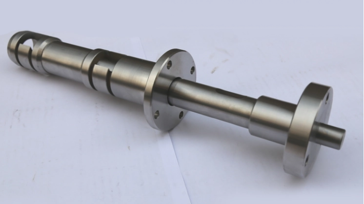
Equipment selection must strictly follow the 10:1 gauge maker's rule. Your measurement device must be ten times more precise than the tolerance you are measuring. If your engineering drawing specifies a diameter tolerance of 0.01mm, your inspection gauge must be capable of reading to a resolution of 0.001mm. Violating this rule introduces unacceptable levels of measurement uncertainty. You end up measuring the noise of the gauge rather than the actual dimension of the part.
Mapping specific inspection technologies to standard International Tolerance (IT) grades helps standardize equipment selection across your facility. Different IT grades demand entirely different metrology approaches.
IT Grade Range | Typical Tolerance (mm) | Recommended Inspection Equipment | Primary Application |
|---|---|---|---|
IT10 - IT12 | ±0.100 to ±0.300 | Digital Calipers, Tape Measures | Rough turning, non-critical lengths, clearance holes. |
IT7 - IT9 | ±0.020 to ±0.080 | Micrometers, Go/No-Go Gauges, Optical Comparators | Standard shafts, threaded components, general assembly fits. |
IT5 - IT6 | ±0.005 to ±0.015 | Standard CMM, Dial Bore Gauges, Vision Systems | Bearing journals, dowel pins, precision locating features. |
IT2 - IT4 | ±0.001 to ±0.004 | High-Accuracy CMM, Dedicated Form Testers, Laser Micrometers | Hydraulic spools, aerospace actuators, high-speed spindles. |
Different measurement tools perform differently across various material classes. Cross-material measurement variability requires careful attention. Hardened steel behaves differently than soft Delrin or PTFE under a tactile probe. Material hardness directly impacts measurement accuracy. A ruby stylus might deflect slightly when contacting hardened tool steel, requiring software compensation. That same stylus might physically indent or mar the surface of a soft aluminum or plastic component, yielding an artificially small diameter reading.
Consider the following material-specific measurement behaviors:
Hardened Tool Steels (D2, A2): High resistance to probe deflection. Requires minimal stabilization time if machined with high-pressure coolant.
Austenitic Stainless Steels (304, 316): Prone to work hardening and localized heat retention. Requires extended thermal soaking before final CMM inspection.
Engineering Plastics (PEEK, Delrin): Highly susceptible to deformation from micrometer anvil pressure. Non-contact vision systems are strongly recommended.
Aluminum Alloys (6061, 7075): High coefficient of thermal expansion. A 100mm diameter part will grow significantly if measured at 30°C instead of 20°C.
You must adjust inspection protocols based on material properties. Materials with high thermal expansion coefficients require adequate stabilization times before measurement. If an aluminum shaft comes out of the machine at 35°C and is immediately measured, it will measure significantly larger than its true size at the standard 20°C inspection temperature. Thermal soaking in a controlled environment is mandatory for accurate results.
Evaluating the return on investment for on-machine probing is necessary for modern scalability. Spindle-mounted probes allow for real-time tool wear compensation and automated zero-point positioning. By measuring the part while it remains clamped in the chuck, the machine can automatically update tool offsets and perform a finish pass. This drastically reduces scrap rates and manual intervention.
Determine the trade-offs between end-of-line statistical batch sampling and mandatory 100% inspection requirements. Aerospace, medical, and automotive safety components often mandate 100% inspection with full traceability for every single serial number. Commercial and industrial parts usually rely on statistical sampling to maintain high throughput while still guaranteeing acceptable quality levels across the batch.
Bridging the gap between manual CNC programming, machine setup, and initial dimensional validation is where most batch-wide defects originate. If the first part off the machine contains a dimensional error or a misunderstood GD&T callout, and production continues, you will scrap the entire run. Relying solely on the machinist's own micrometer check for the first part is a high-risk strategy.
Mitigation requires mandating rigorous First Article Inspection (FAI) protocols. The first part must be removed from the machine, cleaned, thermally stabilized, and inspected in the quality lab using a CMM or form tester. Continuous production runs must not be authorized until the FAI report shows 100% compliance with all drawing specifications. This hard stop prevents cascading setup errors.
Shop-floor temperature fluctuations severely impact both the machined part and the metrology equipment. Metal expands and contracts with temperature changes. A 5°C shift in ambient shop temperature from morning to afternoon will measurably change the dimensions of a large steel shaft. Furthermore, the scales and structures of the CMM itself are subject to thermal distortion.
Mitigation involves establishing isolated, temperature-controlled metrology labs. These labs must maintain a strict 20°C (68°F) environment with controlled humidity. Humidity control is equally important. High humidity environments accelerate rust formation on bare steel parts and cast-iron surface plates. Metrology labs should maintain relative humidity between 40% and 50%. Furthermore, isolate the inspection room from shop floor vibrations. Heavy stamping presses or roughing lathes operating nearby transmit low-frequency vibrations through the concrete floor, disrupting high-magnification optical comparators and sensitive form testers.
Maintaining ISO 17025 compliance and NIST traceability for all measurement instruments is non-negotiable. An uncalibrated micrometer or a CMM with a drifted probe matrix provides false confidence. Using degraded equipment means you are making pass/fail decisions based on fabricated data.
Mitigation demands implementing strict, documented calibration schedules. Shop-floor gauges, gauge blocks, and high-end lab equipment must be verified against known standards at regular intervals. Implement a digital gauge management system to track calibration expiration dates. Any gauge found out of calibration must be immediately quarantined. You must perform a root cause analysis on all parts measured with that gauge since its last known good calibration.
Human error plagues manual measurement techniques. Inconsistent micrometer pressure, slight angular misalignment of calipers, and misreading dial indicators skew data heavily. If three different operators measure the same diameter and get three different results, your measurement system is fundamentally broken.
Mitigation requires conducting routine Repeatability and Reproducibility (Gauge R&R) studies. These statistical studies isolate and quantify equipment variation and operator-induced variance. If the Gauge R&R study shows variance exceeding 10% of the total tolerance band, you must correct it through targeted operator training, standardizing measurement procedures, or upgrading to automated, fixture-based inspection methods.
Require detailed First Article Inspection (FAI) reports mapped directly to your CAD models before approving any full-scale production runs.
Demand statistical process control (SPC) data, including Cp and Cpk values, for all critical-to-function dimensions on ongoing orders.
Audit supplier metrology labs to verify they utilize dedicated form testers for rotational parts with tight cylindricity or runout tolerances.
Update all engineering drawings to clearly define datum structures, eliminating ambiguity during the inspection setup phase.
A: Standard tolerances typically range from ±0.125mm for rough turning down to ±0.010mm for precision finishing. High-precision applications, such as aerospace or medical components, often require tolerances as tight as ±0.005mm. The achievable tolerance depends heavily on the machine's condition, tooling, material, and thermal stability.
A: Accurate roundness measurement requires a dedicated spindle-based form tester. The part rotates on a highly precise air bearing while a stylus measures surface deviations. Standard micrometers or calipers cannot detect odd-numbered lobing, like three-jaw chuck distortion, and should not be used for critical roundness verification.
A: CMMs provide the comprehensive 3D mapping required to verify complex Geometric Dimensioning and Tolerancing (GD&T) callouts. While a micrometer checks basic diameter, a CMM simultaneously verifies cylindricity, concentricity, and total runout relative to specific datums. This ensures the piston shaft functions perfectly within its cylinder assembly.
A: Primary factors include tool wear, thermal expansion of the machine and the workpiece, excessive chucking pressure causing part distortion, material inconsistencies, and machine vibration. Inadequate coolant flow also causes localized heating, leading to dimensional drift during the active machining cycle.
A: Clear datum selection dictates exactly how the part must be fixtured during inspection. If datums are inaccessible or poorly defined, inspectors cannot align the part correctly. Design for Inspection (DFI) ensures that critical features and reference datums can be easily reached by probes and micrometers without interference.
A: Metals expand and contract with temperature changes. Measuring a warm aluminum part straight out of the machine yields a larger diameter than its true size at room temperature. Accurate inspection requires thermally soaking parts in a temperature-controlled lab, typically 20°C, to ensure measurement repeatability and accuracy.


