

Views: 0 Author: Site Editor Publish Time: 2026-10-23 Origin: Site


Sourcing high-tolerance cylindrical components requires aligning part geometry with the correct machining kinematics. Selecting the wrong machine architecture guarantees compromised quality, secondary operation delays, or inflated production times. Defaulting to standard conventional lathes for complex, micro-sized, or slender parts inevitably leads to tool deflection, poor surface finish, and scrapped runs. Conversely, over-specifying Swiss turning for standard, stout geometries unnecessarily complicates setups and restricts material choices.
Engineering teams must evaluate component designs against specific machine capabilities to optimize manufacturing outcomes. This guide establishes a technical, evidence-based framework for evaluating when to specify Swiss versus conventional turning. We will analyze length-to-diameter (L:D) ratios, micro-machining requirements, and production volume to ensure the chosen manufacturing method aligns with dimensional requirements and operational scale.
Kinematic Difference: Conventional turning moves the tool along the workpiece, while Swiss turning advances the workpiece through a guide bushing past stationary tooling, eliminating deflection for long, slender components.
Geometry Thresholds: The length-to-diameter (L:D) ratio is the primary technical threshold; parts exceeding a 3:1 ratio typically require Swiss machining to maintain tight tolerances.
Micro-Machining Superiority: Swiss turning is uniquely capable of handling exceptionally small, intricate parts that conventional chucks would crush or fail to grip securely.
Volume Economics: Conventional turning is more cost-effective for shorter, larger-diameter parts and lower production volumes due to faster setup times and lower tooling complexity.
Production Scale: Production economics depend heavily on production volume; Swiss machines have higher initial setup costs but significantly lower per-part cycle times at scale due to simultaneous multi-axis operations.
Conventional turning relies on a fundamental workholding principle where the material is clamped rigidly at one end using a chuck or collet system. The machine spindle rotates the material at high speeds while cutting tools advance along the Z-axis (length) and X-axis (diameter) to shear away material. For longer components, operators engage a tailstock at the opposite end of the workpiece to provide additional structural support.
The primary limitation of this architecture lies in the physics of radial cutting forces. As the cutting tool engages the spinning material, it generates a radial force that pushes the workpiece away from the tool insert. When machining unsupported lengths, this radial force causes the material to bend slightly. This bending, known on the shop floor as deflection, creates severe manufacturing defects. Deflection manifests as dimensional taper, where the diameter of the part increases the further the tool moves from the chuck. It also induces harmonic vibration, or chatter, which destroys surface finish and accelerates tool wear.
Standard lathes excel when machining rigid, stout components where the clamping force of the jaws can securely hold the mass of the billet without distorting it. They are designed for heavy material removal rates, utilizing large, rigid cutting tools to rapidly rough out shapes from large-diameter bar stock or heavy castings. When evaluating CNC Turning Parts, conventional machines remain the standard for components that do not suffer from cantilever-induced deflection. The rigid setup allows for aggressive depths of cut, making short work of tough alloys like Inconel or hardened tool steels.
Swiss turning completely inverts the conventional kinematic model. Instead of the material remaining stationary in the Z-axis while the tool moves, the material itself advances. The defining feature of a Swiss-type lathe is the guide bushing. Bar stock is gripped by a sliding headstock, which pushes the material through a stationary guide bushing. The cutting tools are mounted on a gang plate positioned mere millimeters from the face of this bushing.
This architectural difference fundamentally changes the machining physics. Because the cutting action occurs immediately adjacent to the point of support, radial cutting forces are absorbed entirely by the guide bushing rather than the bar stock. The material never has the opportunity to bend. This allows for the machining of incredibly long, slender components with zero deflection, taper, or chatter. You can turn a pin that is 0.125 inches in diameter and 4 inches long without any dimensional deviation from end to end.
Modern Swiss machines integrate extensive live tooling and independent sub-spindles. This configuration allows the machine to perform simultaneous milling, drilling, tapping, and turning operations. A part can be completely machined on the main spindle, cut off, transferred to the sub-spindle, and back-worked while the main spindle begins the next part. This "done-in-one" capability eliminates the need to move parts to secondary milling centers. It drastically reduces handling time and eliminates the stacking tolerances associated with multiple fixturing setups.
The decision between Swiss and conventional turning begins with part geometry, specifically the length-to-diameter (L:D) ratio. This metric is calculated by dividing the unsupported length of the cut by the diameter of the material. In machining physics, a 3:1 ratio is widely considered the threshold for conventional turning stability. A 1-inch diameter part protruding 3 inches can be turned conventionally without significant issue. However, a 0.25-inch diameter part protruding 2 inches has an L:D ratio of 8:1, which will deflect heavily on a standard lathe.
Manufacturing precision CNC turned shaft parts with L:D ratios exceeding 5:1 mandates Swiss turning. Attempting to machine these profiles on a conventional lathe requires complex steady rests or tailstock setups, which often fail to prevent micro-deflection and compromise concentricity. Swiss machines effortlessly handle L:D ratios of 20:1 or higher in a single pass because the tool never cuts more than a few thousandths of an inch away from the rigid support of the guide bushing.
Micro-machining presents another absolute boundary. Components used in medical implants, aerospace connectors, and electronic pins often feature diameters under 0.100 inches. Conventional three-jaw chucks cannot grip these micro-diameters without crushing the material or causing severe runout. Swiss collets hold the stock securely behind the guide bushing, feeding it precisely without applying destructive radial pressure to the finished surfaces.
Conversely, Swiss machines face strict maximum bar capacity limitations. The guide bushing mechanism requires the bar stock to pass through the spindle bore. Most standard Swiss lathes max out at 1.25-inch to 1.5-inch (32mm to 38mm) outside diameter (OD). While specialized heavy-duty Swiss machines exist, any component exceeding 2 inches in diameter automatically defaults to conventional turning, which can easily chuck billets exceeding 10 inches in diameter.
Dimensional accuracy requirements heavily influence machine selection. Swiss turning centers routinely hold diametrical tolerances of ±0.0001 inches (0.0025mm) straight off the machine. The extreme rigidity provided by the guide bushing, combined with the thermal stability of the cutting environment, allows for exceptional repeatability across thousands of parts. Operators can set the machine, dial in the offsets, and trust that the dimensions will hold steady throughout the shift.
Conventional turning typically holds tolerances around ±0.0005 inches to ±0.001 inches, depending on the material, tool wear, and operator skill. While conventional lathes can achieve tighter tolerances on short, rigid parts, they struggle to maintain those tolerances across long production runs without constant tool offset adjustments. Thermal expansion of the workpiece during heavy roughing passes also introduces dimensional variations that are difficult to control.
Surface finish capabilities follow a similar pattern. Components like high accuracy CNC piston shafts require micro-inch surface finishes to ensure proper seal engagement and prevent premature wear in hydraulic systems. The absence of vibration in Swiss turning allows standard carbide inserts to generate mirror-like finishes, often eliminating the need for secondary centerless grinding operations. Conventional turning of the same shafts would likely leave microscopic chatter marks, necessitating an entirely separate grinding process to achieve the required surface profile.
Machine setup times dictate the economic viability of production runs. Conventional lathes are relatively fast to set up. An operator can change chuck jaws, load a new program, touch off a few standard turning tools, and run a first article inspection within one to two hours. This makes conventional turning highly economical for prototyping, small batch runs, and low-volume production where the setup time is a significant portion of the overall job time.
Swiss turning requires highly complex, time-consuming setups. The operator must install and precisely adjust the guide bushing tension. This is a critical step that dictates the success of the entire run. If the tension is too tight, the bar seizes and damages the machine. If it is too loose, the part chatters and fails inspection. Additionally, Swiss setups often involve touching off 15 to 25 different tools across multiple axes and synchronizing the handoff between the main and sub-spindle. A full Swiss setup can take four to eight hours.
However, once running, Swiss machines dominate in cycle time reduction. The ability to perform simultaneous operations drastically cuts per-part machining time. The volume breakeven point typically occurs around 1,000 pieces. For runs below this threshold, the high setup cost of Swiss turning outweighs the cycle time savings. For continuous production runs of 5,000 or 50,000 pieces, the rapid cycle times and "done-in-one" efficiency of Swiss turning make it the undisputed economic choice.
Feature | Conventional Turning | Swiss Turning |
|---|---|---|
Workholding Mechanism | Chuck or Collet (Fixed Z-axis) | Guide Bushing & Sliding Headstock |
Tool Motion | X and Z axes | X and Y axes (Material moves in Z) |
Max L:D Ratio | 3:1 (without tailstock support) | 20:1+ (Zero deflection) |
Average Setup Time | 1 to 2 hours | 4 to 8 hours |
Coolant Type | Water-soluble emulsion | Straight cutting oil |
Ideal Production Volume | Low to Medium (Prototyping to 1,000) | High (1,000+ continuous pieces) |
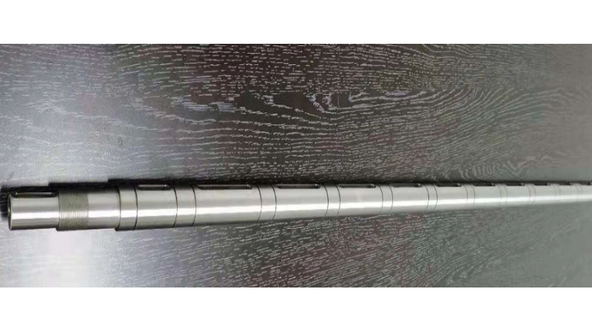
The mechanical reliance on the guide bushing in Swiss turning dictates strict raw material requirements. The bar stock must slide continuously through the bushing with exact clearance. If the bar diameter varies, it will either jam inside the bushing, causing catastrophic machine crashes, or run loosely, destroying part tolerances and surface finish. The clearance between the bar and the bushing is often measured in ten-thousandths of an inch.
Consequently, Swiss machining strictly requires centerless ground bar stock, typically held to h8 or h9 dimensional tolerances. This precision raw material carries a premium cost and often requires longer lead times from metal suppliers. Attempting to run standard extruded or cold-rolled stock through a Swiss guide bushing is a guaranteed path to failure. The inconsistencies in the raw material will immediately translate into scrapped parts.
Conventional turning centers possess no such limitations. Because the material is clamped statically in a chuck, the machine easily handles out-of-round, extruded, or lower-grade rough bar stock. The chuck jaws simply conform to the irregular shape, and the cutting tool machines the OD to the required dimension. This flexibility allows manufacturers to utilize cheaper raw materials, significantly lowering upfront supply chain costs for parts that do not require Swiss kinematics.
Machining generates intense heat, and the two turning methods manage this thermal dynamic differently. Swiss machines almost exclusively utilize straight cutting oils. The primary function of this oil is to provide extreme lubricity between the rotating bar stock and the stationary guide bushing. Without this lubricity, the friction would cause the materials to gall and weld together. While straight oil provides superior lubricity, it dissipates heat slower than water-based fluids, requiring specialized high-pressure delivery systems to blast chips away from the cutting zone.
Conventional lathes utilize water-soluble coolant emulsions. These fluids are designed for maximum heat extraction. When roughing large diameters of tough materials like Titanium Grade 5 or 17-4 PH Stainless Steel, conventional lathes generate massive thermal loads. Water-soluble coolants flood the cutting zone, rapidly carrying heat away from the tool insert and preventing thermal deformation of the workpiece.
These cooling strategies directly impact tool life. The combination of extreme rigidity at the cut and heavy cutting oils in Swiss machining often extends carbide insert life significantly. The lack of vibration prevents micro-chipping of the cutting edge. In high-volume production, this extended tool life reduces consumable costs and minimizes machine downtime required for tool changes. Operators can run Swiss machines lights-out overnight with confidence that the tools will survive until morning.
Engineering teams frequently introduce unnecessary costs by failing to align their component designs with the realities of machine kinematics. A common DFM blind spot is specifying Swiss turning for large OD parts simply because the drawing contains tight tolerances. If the part exceeds 1.5 inches in diameter, it physically will not fit in most standard Swiss machines, forcing suppliers to quote the job on slower, multi-setup conventional equipment.
Another frequent error involves failing to design custom lathe turned metal parts around standard centerless ground bar stock sizes. If an engineer specifies a maximum OD of 0.485 inches, the manufacturer must purchase 0.500-inch ground stock and turn the entire length down to 0.485 inches. If the design allows the maximum OD to remain at 0.500 inches, the manufacturer can leave the raw bar stock untouched on that surface, saving significant cycle time and tool wear.
Over-tolerancing non-critical dimensions also creates implementation risks. Applying a blanket ±0.0005-inch tolerance across an entire drawing forces the supplier to utilize Swiss turning or secondary grinding, even if the part geometry is short and stout. Engineers must isolate tight tolerances only to critical mating surfaces, allowing the manufacturer the flexibility to choose the most efficient machining method for the overall part.
Selecting the right manufacturing partner requires looking beyond basic machine lists. When vetting suppliers for high-tolerance cylindrical components, assess the age and rigidity of their machine tools. Older Swiss machines with worn ball screws cannot hold the micro-inch tolerances required for modern aerospace or medical components, regardless of operator skill. You need partners who regularly calibrate their equipment and invest in rigid, modern platforms.
Evaluate the availability of multi-axis equipment. A supplier operating 7-axis or 9-axis Swiss centers can execute complex cross-drilling, off-center milling, and angled features in a single setup. Suppliers limited to basic 3-axis lathes will require secondary milling operations, introducing fixturing errors and increasing lead times. The ability to drop a finished part complete from the machine is the ultimate goal.
Finally, inspect their in-house metrology capabilities. Manufacturing precision components is irrelevant if the supplier cannot verify the dimensions. Ensure the partner utilizes optical comparators, vision systems, and Coordinate Measuring Machines (CMMs) capable of measuring down to the micron level. A robust quality control department is the only safeguard against receiving non-conforming batches.
Calculate the L:D ratio for all unsupported turned features on your current component drawings to identify immediate candidates for Swiss machining.
Audit your material specifications to ensure maximum outer diameters align with standard fractional centerless ground bar stock sizes, eliminating unnecessary OD turning passes.
Submit your CAD files and 2D drawings to a qualified manufacturing partner for a technical DFM review and exact cycle-time analysis.
Request a breakeven volume analysis from your supplier to determine the exact production quantity where Swiss setup times are offset by cycle time savings.
A: Swiss turning machines typically accommodate bar stock between 1.25 to 1.5 inches (32mm to 38mm) in diameter. While some specialized, heavy-duty Swiss lathes can reach up to 2 inches, any component exceeding these dimensions physically requires conventional CNC turning equipment.
A: The raw material must slide smoothly through the stationary guide bushing with exact, minimal clearance. Variations in standard extruded bar diameter cause the material to either jam inside the bushing or vibrate excessively, which destroys dimensional tolerances and surface finishes.
A: Yes, but only on short, rigid parts with low length-to-diameter ratios. On longer parts, conventional lathes suffer from radial tool deflection, making Swiss-level tolerances impossible to achieve without relying on secondary centerless grinding operations.
A: Precision shafts frequently exceed a 3:1 or even 5:1 length-to-diameter ratio. This extreme geometry makes them the primary use case for Swiss turning, as the guide bushing prevents deflection, ensuring absolute straightness and concentricity across the entire length.
A: Swiss machines require significantly longer setup times due to guide bushing calibration and complex multi-axis tooling arrays. This makes them expensive for short runs but highly economical for high-volume production, where rapid cycle times quickly offset the initial setup investment.
A: Swiss turning often eliminates the need for secondary operations. The extreme rigidity of the guide bushing allows the machine to hold tight tolerances and achieve micro-inch surface finishes in a single setup, bypassing the need for secondary centerless grinding.


